Bigme B6 E-Ink Tablet Teardown

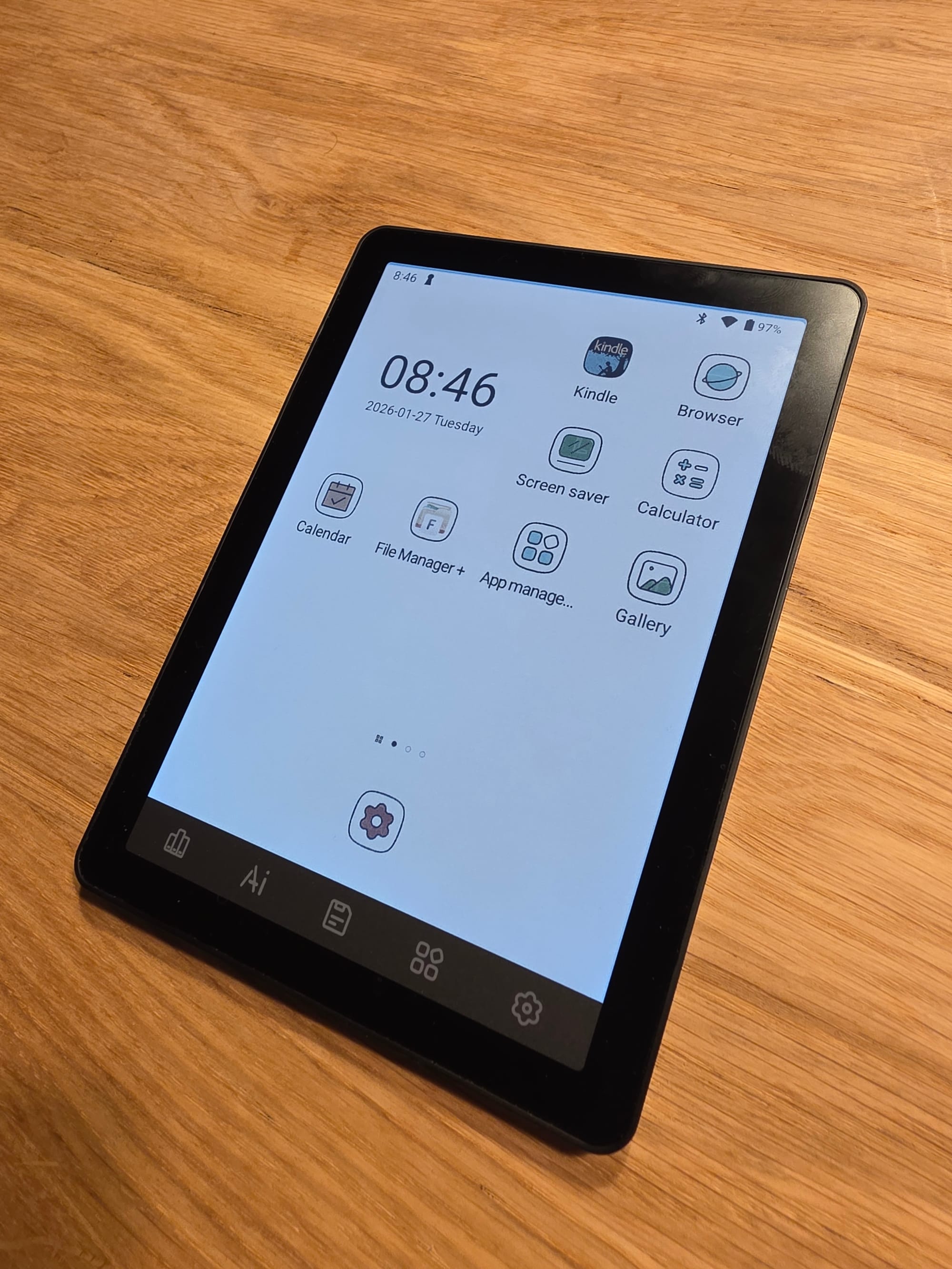
For another project I was interested in looking at cheap E-Ink Android tablets and landed on the Bigme B6 Color. A 6" color E-Ink tablet with a 1072x1448 resolution screen. The black and white portion is advertised with 300ppi and the color portion with 150ppi. So you get less color capable pixels overall, which becomes apparent in the slightly washed out looking colors.
Though overall its a decent screen and for around 160$ a pretty good price for a slow but passable Android tablet with a fairly recent E-Ink screen. The stock software kinda sucks but the bootloader can be unlocked to root the device with a tool like Magisk. Then its quick work to debloat it. Though official OTA updates seem to fail after rooting so be aware of that.
You can enter the Mediatek recovery mode for usage with the various Mediatek USB flashing utilities by shutting off the tablet, removing USB, holding the power button and immediately re-attaching USB. Just don't press too long or it will boot the tablet normally instead, usually holding around 2-3 seconds was fine. You might have to retry a few times.
You probably want to unlock the bootloader in the developer settings first though if you want to make changes.
I did not see much info on this cheap little device so I thought I do a teardown and document a bit whats inside. Overall it seems quite hackable as its really easy to open.
The back is just one big plastic snap on shell, remove the SDCard tray, then go in with some plastic prying tool to unlatch the plastic latches and go around the whole device until they are all undone.
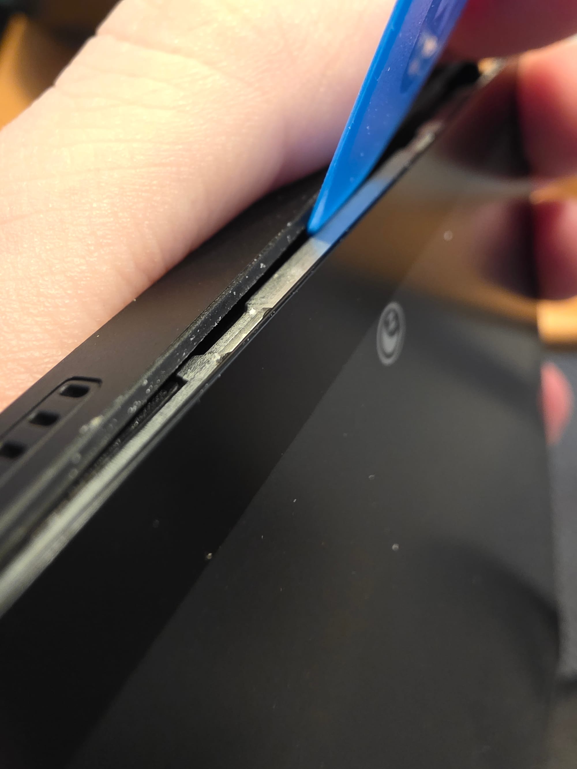
Thats it, you now have access to pretty much everything except the screen itself which seems to be bonded to the metal frame.
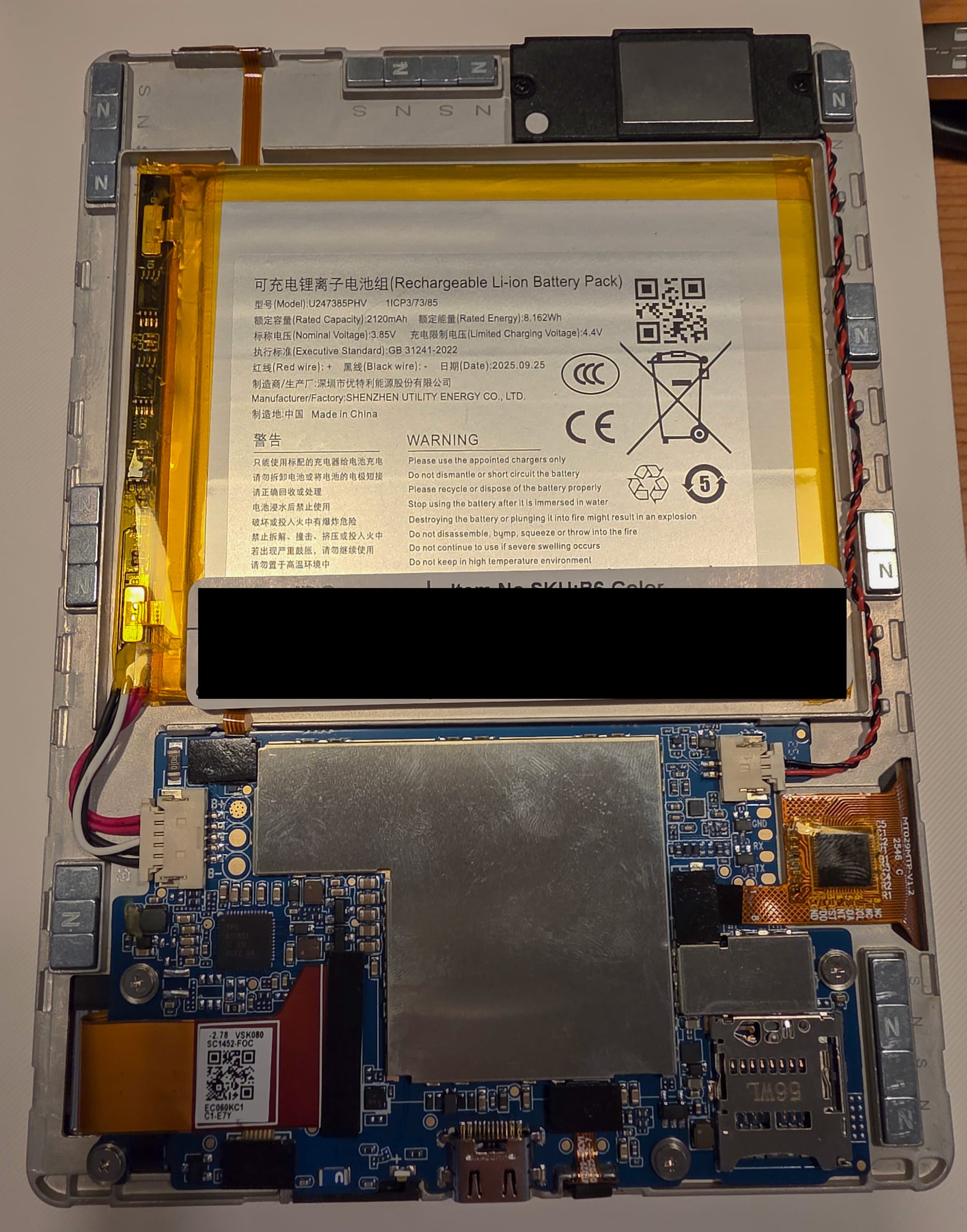
You can see there is a lot of magnets placed around the frame, they enable you to stick the tablet onto a steel surface like a fridge door. They are not glued in and are easy to remove if you don't want them in the device for whatever reason.
The battery is mildy glued down but would be easy to remove with a bit of prying underneath.
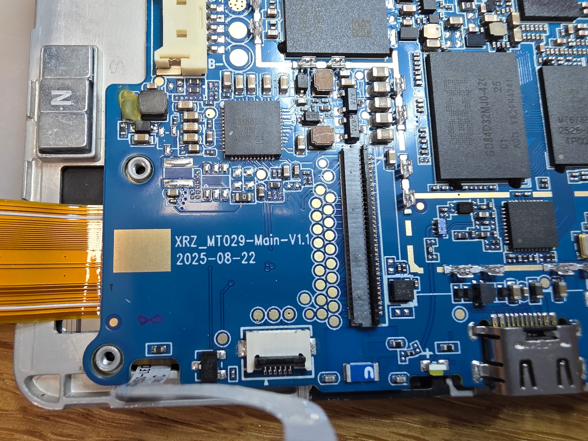
The battery cable is quick to remove and next to the connector you get huge test pads for the B+, B- and NTC. The battery is single cell 4.2V. If you wanted to wall power the device this would be a good spot to solder in a little buck converter if you don't want to crimp a fitting cable or want to power it with the shell in place, doing a little drill hole in that spot would make it easy to run a hidden power cable behind the device in a fixed installation situation.
Unfortunately the device does not power up with the battery disconnected and only USB-C connected, so for wall powering going to the battery terminal is a must.
Most of the ICs are under various shields. Removing the shields is easy though as they are just held in place by little clips and are not soldered in permanently.
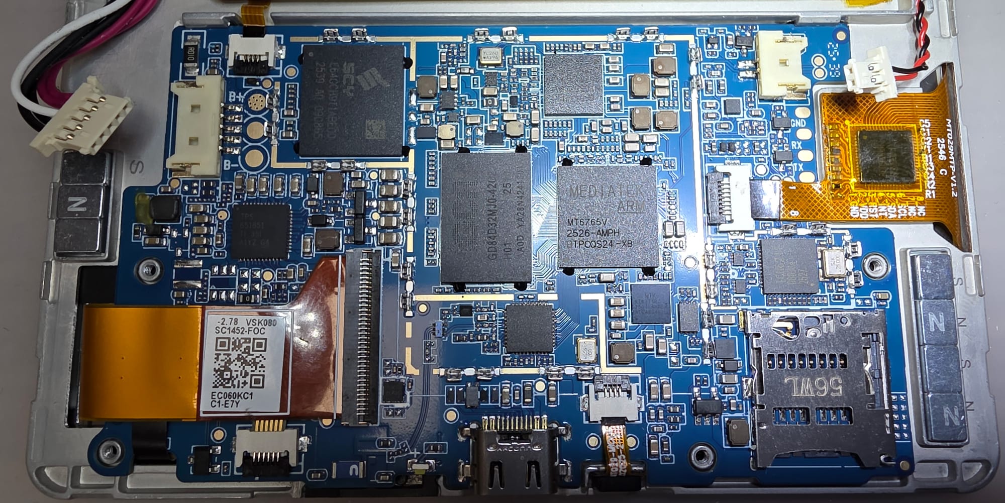
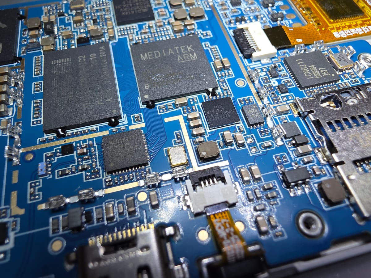
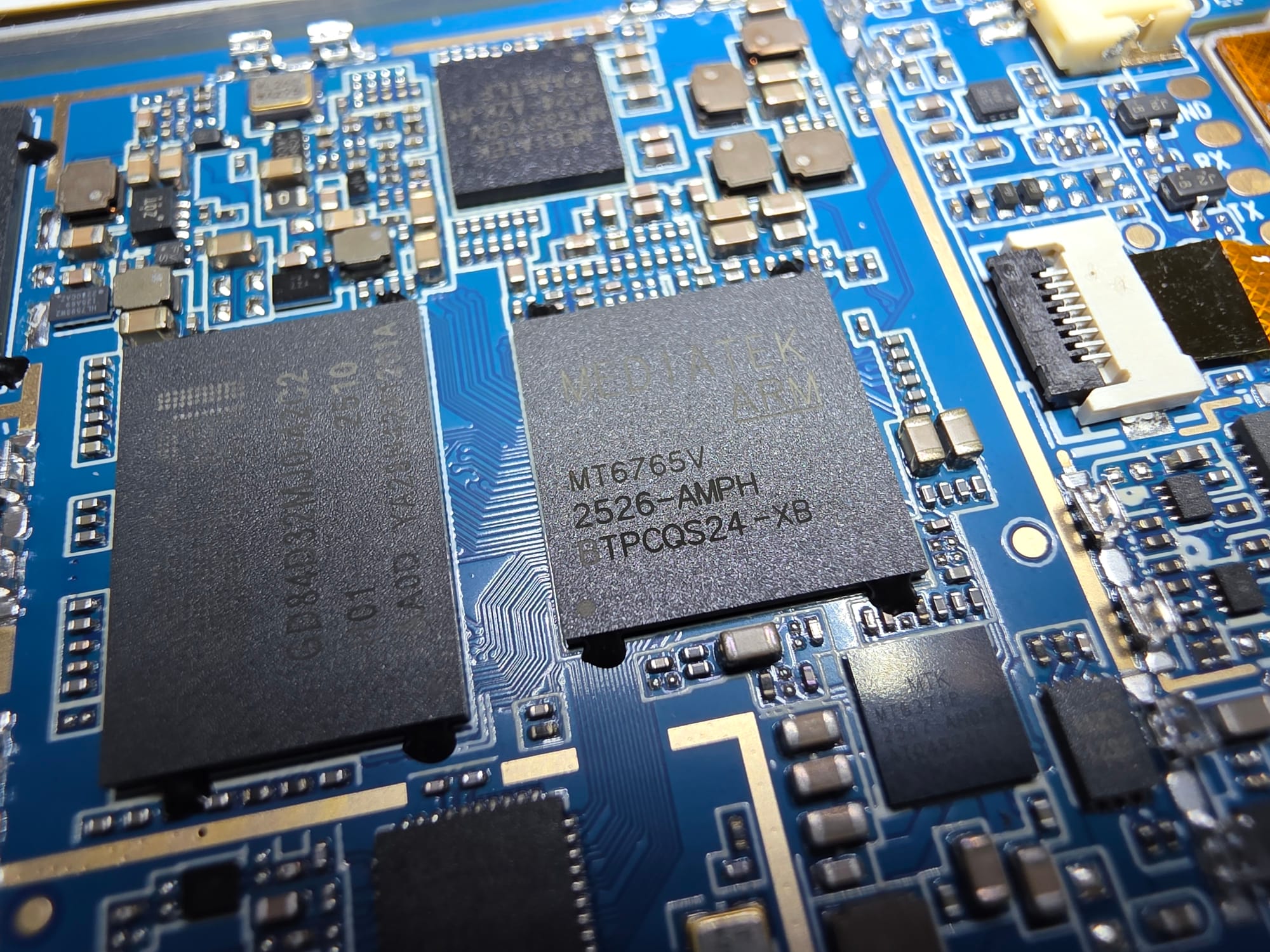
The main SoC is a Mediatek MT6765V aka Helio P35, a pretty old Cortex‑A53 SoC from 2018.
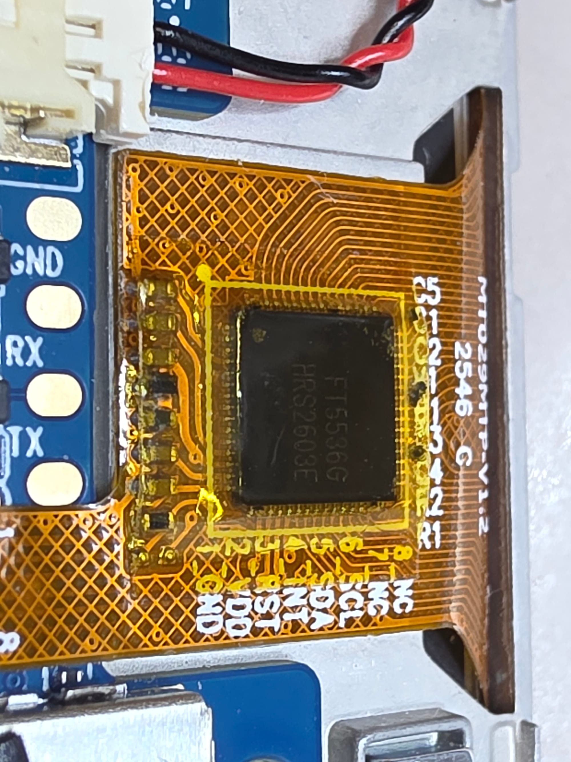
To the right next to the captouch FPC are pads for a UART port. I have not probed it but quite likely that its for the Mediatek SoC, good chance of having a console on there for factory flashing.
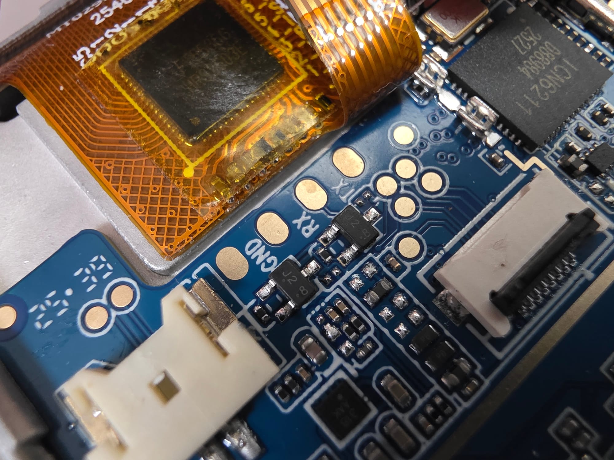
Close by to the right we can also see a ICN6211, a pretty prolific IC for DSI to parallel RGB conversion. That will be driving the screen itself. The screen connector is on the other side though, a bit of an odd place to breakout to the parallel bus and then route all those signals across the entire PCB.
On the power side its mostly part specific PMICs.
From Mediatek for their SoCs we got a MT6371P and MT6357CRV.
The MT6371P is likely responsible for battery charging, it also does USB-PD (in theory) and backlight control. Though many of these things that PMIC does can also be done by the MT6357CRV not clear why they added a second PMIC for that.
Close to the E-Ink connector is an E-Ink specific TI TPS651851 which seems to be made for that particular series of panels.
For WiFi and Bluetooth connectivity they are using a MT6631.
Captouch controller is a FocalTech FT5536G, no public hits on that but not uncommon for these. Probably similar to the FT5546.
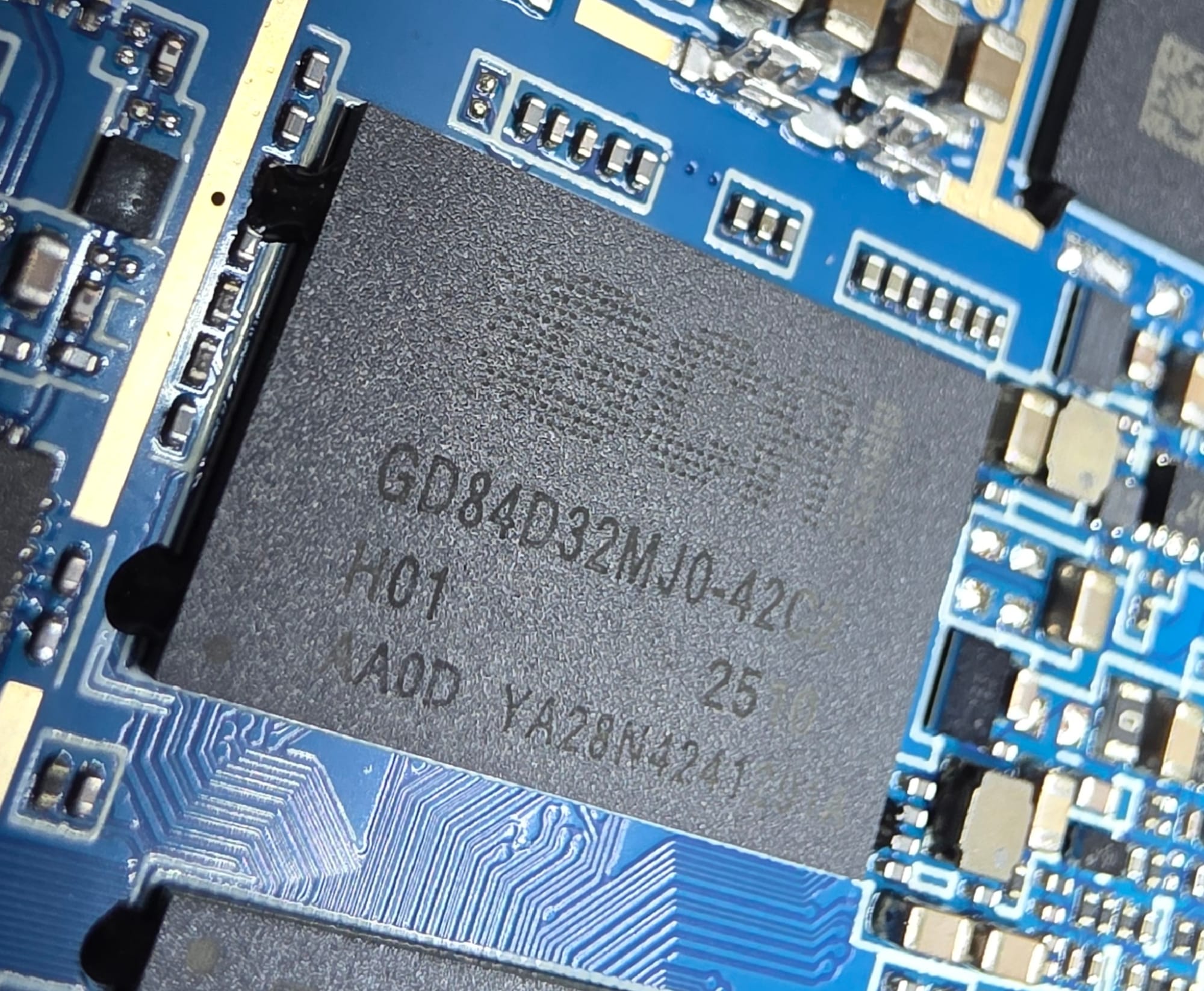
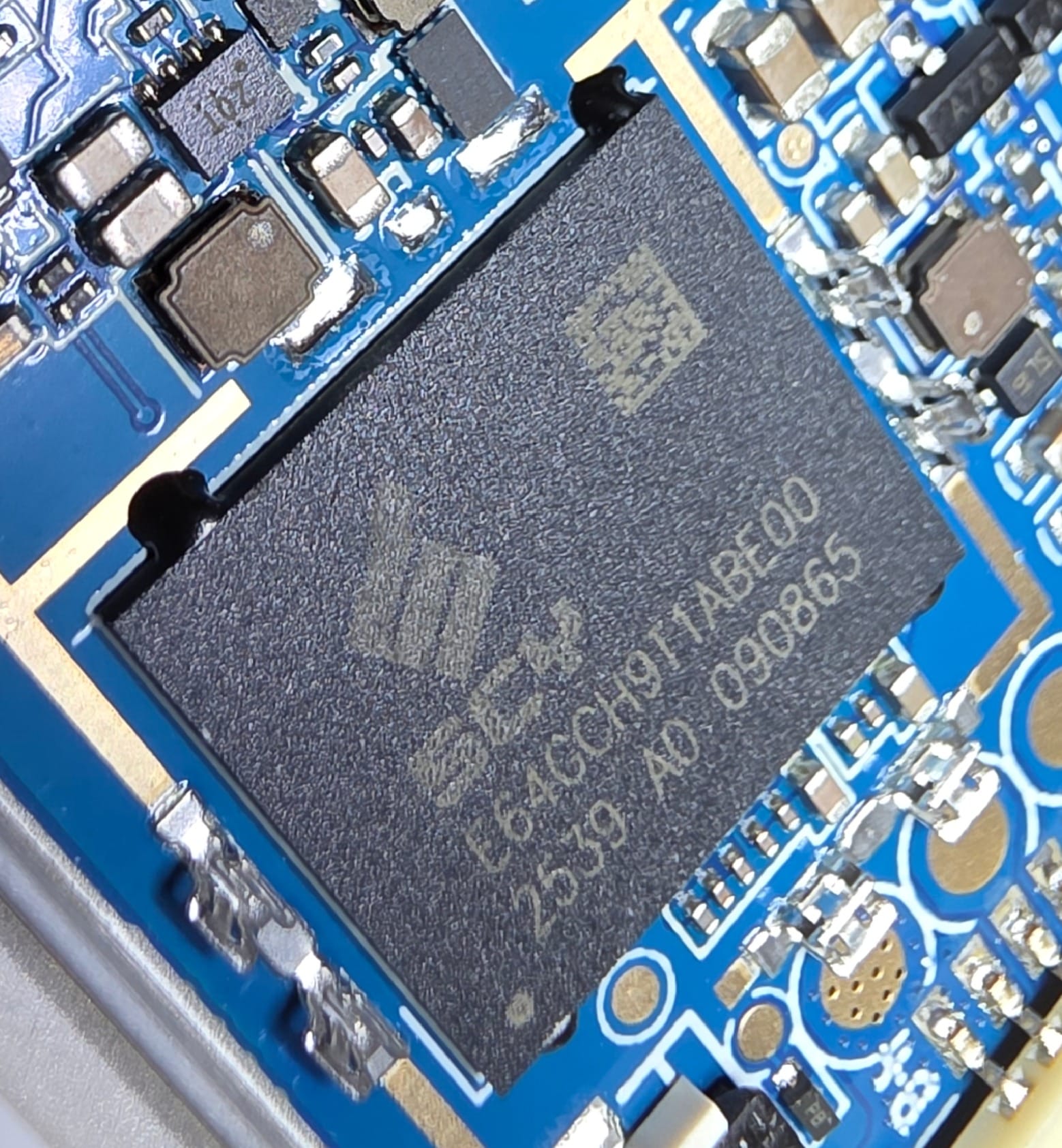
Other than that its just RAM(?) from "GCAI" and eMMC(?) from "SCY". Neither brand I heard of before.
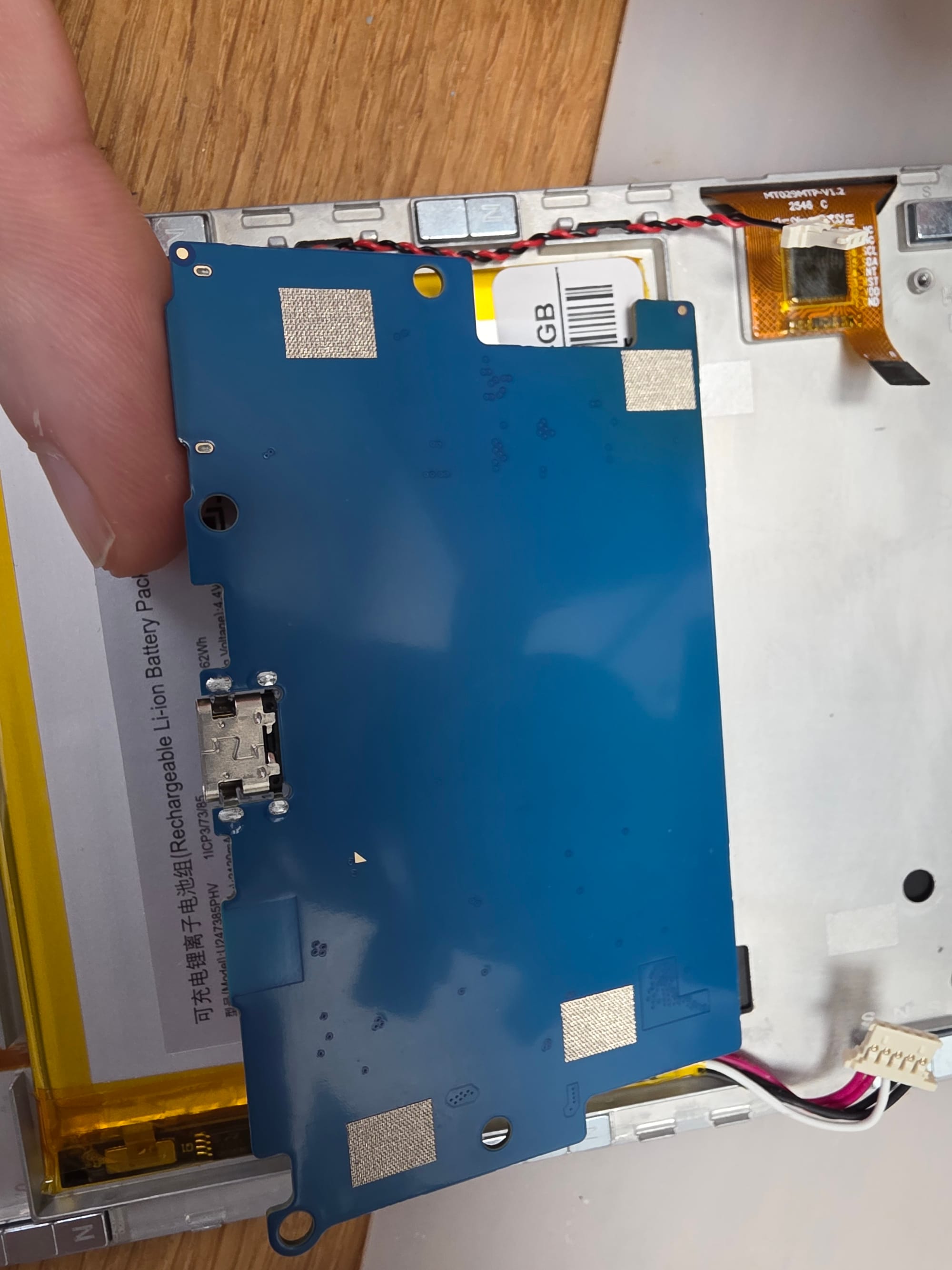
The underside is completely free from parts except for some grounding pads.
If you ever wondered how those SIM eject pin holes work. Here is the mechanism in action (SD card in this case but its the same concept).